|
| No dimensional drawings!
Unit:
|
|
|
| No dimensional drawings!
Unit:
|
4 分類
4.1 表1中所列的螺紋量規名稱、代号、使用規則适用于本标準。
4.2 檢驗工件螺紋用的光滑極限量規見附錄A的規定。
表1
名稱 | 代号 | 使用規則 |
通端螺紋塞規 | T | 應與工件内螺紋旋合通過 |
止端螺紋塞規 | Z | 允許與工件内螺紋兩瑞的螺紋部分旋合,旋合量應不超過二個螺距(退出量規時測定)。若工件内螺紋的螺距少于或等于三個,不應完全旋合通過 |
通端螺紋環規 | T | 應與工件外螺紋旋合通過 |
止端螺紋環規 | Z | 允許與工件外螺紋兩端的螺紋部分旋合,旋合量應不超過二個螺距(退出量規時測定)。若工件内螺紋的螺距少于或等于三個,不應完全旋合通過 |
“校通-通”螺紋塞規 | TT | 應與通端螺紋環規旋合通過 |
“校通-止”螺紋塞規 | TZ | 允許與通端螺紋環規兩端的螺紋部分旋合,旋合量應不超過一個螺距(退出量規時測定) |
“校通-損”螺紋塞規 | TS | |
“校止-通”螺紋塞規 | ZT | 應與止端螺紋環規旋合通過 |
“校止-止”螺紋塞規 | ZZ | 允許與止端螺紋環規兩端的螺紋部分旋合,旋合量應不超過一個螺距(退出量規時測定) |
“校止-損”螺紋塞規 | ZS |
5 符号
表2中所列的符号及說明适用于本标準。
表2
符号 | 說明 |
D、d | 工件内、外螺紋的大徑 |
D2、d2 | 工件内、外螺紋的中徑 |
D1 | 工件内螺紋的小徑 |
es | 工件外螺紋中徑的上偏差 |
EI | 工件内螺紋中徑的下偏差 |
H | 工件内、外螺紋的原始三角形高度 |
Td2 | 工件外螺紋中徑的中徑公差 |
TD2 | 工件内螺紋中徑的中徑公差 |
P | 工件内、外螺紋的螺距 |
TR | 通端螺紋環規、止端螺紋環規的中徑公差 |
TPL | 通端螺紋塞規、止端螺紋塞規的中徑公差 |
TCP | 校對螺紋塞規的中徑公差 |
TP | 螺紋量規的螺距公差 |
ZR | 由通端螺紋環規中徑公差帶的中心線至工件外螺紋中徑上偏差之間的距離 |
ZPL | 由通端螺紋塞規中徑公差帶的中心線至工件内螺紋中徑下偏差之間的距離 |
WGO | 由通端螺紋塞規(或環規)中徑公差帶的中心線至其磨損極限之間的距離 |
WNG | 由止端螺紋塞規(或環規)中徑公差帶的中心線至其磨損極限之間的距離 |
m | 由螺紋環規中徑公差帶的中心線至“校通-通”(或“校止-通”)螺紋塞規中徑公差帶的中心線之間的距離 |
Ta1/2 | 完整螺紋牙型的半角偏差 |
Ta2/2 | 截短螺紋牙型的半角偏差 |
S | 截短螺紋牙型的間隙槽中心線相對于螺紋牙型中心線的允許偏移量 |
F1 | 在截短螺紋牙型的軸向剖面内,由中徑線至牙側直線部分頂端(向牙頂一側)之間的徑向距離 |
F2 | 在截短螺紋牙型的軸向剖面内,由中徑線至牙側直線部分末端(向牙底一側)之間的徑向距離 |
b1 | 内螺紋完整牙型大徑處的間隙槽寬度 |
b2 | 外螺紋完整牙型小徑處的間隙槽寬度 |
b3 | 内螺紋截短牙型大徑處的間隙槽寬度和外螺紋截短牙型小徑處的間隙槽寬度 |
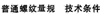
6 螺紋量規的螺紋牙型
6.1 完整螺紋牙型
6.1.1 适用于檢驗工件内螺紋作用中徑及大徑的通端螺紋塞規的螺紋牙型見圖1。圖示僅供圖解說明。
6.1.2 适用于檢驗新制通端螺紋環規作用中徑的“校通-通”螺紋塞規的螺紋牙型見圖1。圖示僅供圖解說明。
6.1.3 還用于檢驗新制止端螺紋環規單一中徑的“校止-通”螺紋塞規和“校止-止”螺紋塞規的螺紋牙型見圖1。圖示僅供圖解說明。
6.1.4 适用于檢驗使用中止端螺紋環規單一中徑的“校止-損”螺紋塞規的螺紋牙型見圖1。圖示僅供圖解說明。
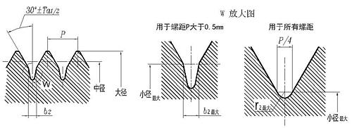
圖1
6.1.5 适用于檢驗工件外螺紋作用中徑及小徑的通端螺紋環規的螺紋牙型見圖2。圖示僅供圖解說明。
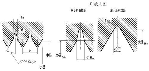
圖2
6.1.6 螺紋牙型間隙槽和槽底的形狀宜由制造商自行确定;螺紋牙型的間隙槽寬度b1最大、b2最大和槽底的曲率半徑r1最大、r2最大見表3。
表3
P | b1最大 | b2最大 | r1最大 | r2最大 |
0.2 | 0.025 | 用曲率半徑r2連接 | 0.014 | 0.029 |
0.25 | 0.031 | 0.018 | 0.036 | |
0.3 | 0.038 | 0.022 | 0.043 | |
0.35 | 0.044 | 0.025 | 0.050 | |
0.4 | 0.050 | 0.029 | 0.058 | |
0.45 | 0.056 | 0.032 | 0.065 | |
0.5 | 0.063 | 0.036 | 0.072 | |
0.6 | 0.075 | 0.15 | 0.043 | 0.086 |
0.7 | 0.088 | 0.17 | 0.050 | 0.100 |
0.75 | 0.094 | 0.19 | 0.054 | 0.110 |
0.8 | 0.100 | 0.20 | 0.058 | 0.110 |
1 | 0.125 | 0.25 | 0.072 | 0.140 |
1.25 | 0.150 | 0.31 | 0.090 | 0.180 |
1.5 | 0.190 | 0.37 | 0.108 | 0.210 |
1.75 | 0.220 | 0.44 | 0.126 | 0.250 |
2 | 0.250 | 0.50 | 0.144 | 0.290 |
2.5 | 0.320 | 0.61 | 0.180 | 0.360 |
3 | 0.400 | 0.75 | 0.217 | 0.430 |
3.5 | 0.480 | 0.88 | 0.253 | 0.500 |
4 | 0.500 | 1.00 | 0.288 | 0.580 |
4.5 | 0.550 | 1.10 | 0.325 | 0.650 |
5 | 0.600 | 1.25 | 0.361 | 0.720 |
5.5 | 0.700 | 1.40 | 0.397 | 0.790 |
6 | 0.800 | 1.50 | 0.433 | 0.860 |
8 | 1.000 | 2.00 | 0.576 | 1.152 |
注: b1最大=P/8;b2最大=P/4;r1最大=0.072P=H/12;r2最大=0.144P。 | ||||
6.2 截短螺紋牙型
6.2.1 适用于檢驗工件内螺紋單一中徑的止端螺紋塞規的螺紋牙型見圖3。圖示僅供圖解說明。
6.2.2 适用于檢驗新制通端螺紋環規單一中徑的“校通-止”螺紋塞規的螺紋牙型見圖3。圖示僅供圖解說明。
6.2.3 适用于檢驗使用中通端螺紋環規單一中徑的“校通-損“螺紋塞規的螺紋牙型見圖3。 圖示僅供圖解說明。
b3=(P/2)-2F2tg30°
圖3
6.2.4 适用于檢驗工件外螺紋單一中徑的止端螺紋環規的螺紋牙型見圖4。圖示僅供圖解說明。
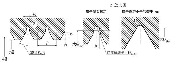
b3=(P/2)-2F2tg30°
圖4
6.2.5 螺紋牙型間隙槽和槽底的形狀宜由制造商自行确定。
6.2.6 螺紋牙型間隙槽寬度b3、在螺紋牙型的軸向剖面内,由中徑線與牙側直線部分頂端(向牙頂一側)之間的徑向距離F1、在螺紋牙型的軸向剖面内,由中徑線與牙側直線部分末端(向牙底一側)之間的徑向距離F2見表4。止端螺紋環規的牙型高度h3 參見附錄B。
表4
P | b3 | F1=0.1P | F2 | |||
尺寸 | 偏差 | 0.1P | 0.15P | 0.2P | ||
0.2 | 止端螺紋環規推薦采用r1連接 | 0.020 | / | / | / | |
0.25 | 0.025 | |||||
0.3 | 0.030 | |||||
0.35 | 0.035 | |||||
0.4 | 0.040 | |||||
0.45 | 0.045 | |||||
0.5 | 0.050 | |||||
0.6 | 0.060 | |||||
0.7 | 0.070 | |||||
0.75 | 0.075 | |||||
0.8 | 0.080 | |||||
1 | 0.100 | |||||
1.25 | 0.3 | ±0.04 | 0.125 | 0.25 | ||
1.5 | 0.4 | 0.150 | 0.30 | |||
1.75 | 0.45 | ±0.05 | 0.175 | 0.35 | ||
2 | 0.5 | 0.200 | 0.40 | |||
2.5 | 0.8 | 0.250 | 0.375 | / | ||
3 | 1.0 | ±0.08 | 0.300 | 0.450 | ||
3.5 | 1.1 | 0.350 | 0.525 | |||
4 | 1.3 | ±0.10 | 0.400 | 0.600 | ||
4.5 | 1.7 | 0.450 | 0.45 | / | ||
5 | 1.9 | 0.500 | 0.50 | |||
5.5 | 2.1 | 0.550 | 0.55 | |||
6 | 2.3 | 0.600 | 0.60 | |||
8 | 3.1 | 0.800 | 0.80 | |||
6.2.7 螺紋牙型的間隙槽見圖5。圖示僅供圖解說明。螺紋牙型的間隙槽中心線相對于螺紋牙型中心線允許有一個偏移量S,其值見表5。當實際偏移量X小于S時,則b3的偏差可以增大,其增大值等于2(S-X)。
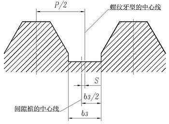
圖5
表5
P | S |
1.25、1.5 | 0.04 |
1.75、2、2.5 | 0.05 |
3、3.5 | 0.08 |
4、4.5、5、5.5、6、8 | 0.10 |
7 公差
7.1 中徑公差
7.1.1 螺紋環規和校對螺紋塞規的螺紋中徑公差帶見圖6。圖示僅供圖解說明。
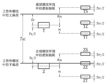
圖6
7.1.2 螺紋塞規的螺紋中徑公差帶見圖7。圖示僅供圖解說明。
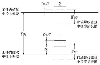
圖7
7.1.3 螺紋塞規、蝶紋環規和校對螺紋塞規的煤紋中徑公差和有關的位笠要素值見表6.
表6
Td2、TD2 | TR | TPL | TCP | m | ZR | ZPL | 螺紋環規 | 螺紋塞規 | ||
WGO | WNG | WGO | WNG | |||||||
24≤Td2、TD2≤50 | 8 | 6 | 6 | 10 | -4 | 0 | 10 | 7 | 8 | 6 |
50<Td2、TD2≤80 | 10 | 7 | 7 | 12 | -2 | 2 | 12 | 9 | 9.5 | 7.5 |
80<Td2、TD2≤125 | 14 | 9 | 8 | 15 | 2 | 6 | 16 | 12 | 12.5 | 9.5 |
125<Td2、TD2≤200 | 18 | 11 | 9 | 18 | 8 | 12 | 21 | 15 | 17.5 | 11.5 |
200<Td2、TD2≤315 | 23 | 14 | 12 | 22 | 12 | 16 | 25.5 | 19.5 | 21 | 15 |
315<Td2、TD2≤500 | 30 | 18 | 15 | 27 | 20 | 24 | 33 | 25 | 27 | 19 |
500<Td2、TD2≤670 | 38 | 22 | 18 | 33 | 28 | 32 | 41 | 31 | 33 | 23 |
注:ZR為負值表示位于圖6中Td2之外,而代入表10和表11要考慮符号。 | ||||||||||
7.2 半角偏差
螺紋塞規和螺紋環規的牙型半角允許偏差見表7。牙型面有效長度内的直線度誤差應不超過半角偏差的公差帶範圍。對公稱直徑小于或等于100mm的螺紋,其直線度誤差的最大值應不大于2μm;公稱直徑大于100mm的螺紋,其直線度誤差的最大值應不大于3μm。
表7
P/mm | Ta1/2(´) | Ta2/2(´) |
0.20 | ±60 | |
0.25 | ±48 | |
0.30 | ±40 | |
0.35 | ±35 | |
0.40 | ±31 | |
0.45 | ±26 | |
0.50 | ±25 | |
0.60 | ±21 | |
0.70 | ±18 | |
0.75 | ±17 | |
0.80 | ±16 | |
1.00 | ±15 | ±16 |
1.25 | ±13 | |
1.50 | ±12 | |
1.75 | ±11 | |
2.00、2.50 | ±10 | ±14 |
3.00 | ±9 | ±13 |
3.50 | ±12 | |
4.00、4.50、5.00 | ±8 | ±11 |
5.50、6.00、8.00 | ±10 | |
7.3 螺距公差
螺紋量規的螺距公差見表8。螺距的實際偏差既可以是“正”的,也可以是“負”的。螺距公差适用于螺紋量規螺紋長度内的任意牙數。
表8
螺紋量規的螺紋長度l/mm | Tp/μm |
l≤14 | 4 |
14<l≤32 | 5 |
32<l≤50 | 6 |
50<l≤80 | 7 |
7.4 公式
7.4.1 螺紋塞規大徑、中徑、小徑的尺寸與偏差的計算公式見表9。
表9
塞規代号 | 大徑 | 中徑 | 小徑 | |||
尺寸 | 偏差 | 尺寸 | 偏差 | 磨損偏差 | ||
T | D+EI+ZPL | ±TPL | D2+EI+ZPL | ±TPL/2 | -WGO | ≤D1+EI |
Z | D2+EI+TD2+TPL/2+2F1 | D2+EI+TD2+TPL/2 | -WNG | |||
7.4.2 螺紋環規大徑、中徑、小徑的尺寸與偏差的計算公式見表10。
表10
環規代号 | 大徑 | 中徑 | 小徑 | |||
尺寸 | 偏差 | 磨損偏差 | 尺寸 | 偏差 | ||
T | ≥d+es+TPL | d2+es-ZR | ±TR/2 | +WGO | D2+es | ±TR/2 |
Z | d2+es-Td2-TR/2 | +WNG | d2+es-Td2-TR/2+2F1 | ±TR | ||
7.4.3 校對螺紋塞規大徑、中徑、小徑的尺寸與偏差的計算公式見表11。
表11
量規代号 | 大徑 | 中徑 | 小徑 | ||
尺寸 | 偏差 | 尺寸 | 偏差 | ||
TT | d+es | ±TPLa | d2+es-ZR-m | ±TCP/2 | ≤D1+es-ZR-m |
TZ | d2+es-ZR+TR/2+2F1 | ±TPL/2 | d2+es-ZR+TR/2 | ≤D1+es-TR/2 | |
TS | d2+es-ZR+WGO+2F1 | d2+es-ZR+WGO | |||
ZT | d+es | ±TPLa | d2+es-Td2-TR/2-m | ≤D1+es-Td2-TR/2-m | |
ZZ | d+es-Td2 | ±TPL | d2+es-Td2 | ≤D1+es-Td2 | |
ZS | d+es-Td2-TR/2+WNG | d2+es-Td2-TR/2+WNG | |||
a.若螺紋牙型的大徑部分是尖的,則可以稍稍削平。于是,大徑尺寸允許小于該下偏差。 | |||||
8 要求
8.1 外觀
螺紋量規測量面的表面上不應有影響使用性能的鏽迹、碰傷、劃痕等缺陷。
8.2 相互作用
螺紋量規測量頭和手柄的聯接應牢固可靠,在正常使用過程中不應出現松動或脫落。
8.3 材料
螺紋量規測量頭的測量面宜采用合金工具鋼、碳素工具鋼等堅硬耐磨的材料制造,并應進行穩定性處理。
8.4 硬度、表面粗糙度
8.4.1 螺紋量規測量頭的測量面硬度應在664 HV~856 HV(或58 HRC~65 HRC)範圍内;對公稱直徑小于或等于3mm的螺紋塞規,其測量頭的測量面硬度應在561 HV~713 HV(或53 HRC~60 HRC)範圍内。
8.4.2 螺紋量規測量面的表面粗糙度Ra值不應大于表12的規定。
表12
名稱 | Ra/μm |
牙側 | 0.2 |
通端螺紋塞規大徑、校對螺紋塞規大徑、通端螺紋環規小徑 | 0.4 |
止端螺紋塞規大徑、止端螺紋環規小徑 | 0.8 |
8.5 螺紋倒鈍
若螺紋量規兩端的牙型不完整,應将牙型修整到為完整牙型。如果做不到,則應有30°倒角。
9 檢驗
9.1 測量條件
本标準中的規定值均以标準的測量條件為準,即:溫度為20℃、測量力為零。
9.2 檢測參數和檢測器具
9.2.1 螺紋塞規各參數采用直接檢測法檢驗,其主要檢測參數和檢測器具見表13。
表13
主要檢測參數 | 檢測器具 |
單一中徑 | 測長儀、量針 |
小徑 | 萬能工具顯微鏡 |
螺距 | 萬能工具顯微鏡、螺距儀 |
牙型半角 | 萬能工具顯微鏡 |
9.2.2 螺紋環規的檢驗應以校對螺紋塞規為準。若發生争議時,應按附錄C中的C.3 處理。若用戶和制造商雙方一緻同意采用其他的測量方法,則螺紋環規的單一中徑尺寸和偏差是有效的。螺紋環規的小徑采用光滑極限塞規檢驗。
Specifications of high strength bolts with large hexagon head, large hexagon nuts, plain washers for steel structures
Self-tappingscrew connections - Specification ofthepilotholediameterand tighteningtorque
Composite sealing gasket material
Corrosion of metals and alloys - Corrosivity of atmospheres - Part 1 : Classification, determination and estimation
Corrosion of metals and alloys - Corrosivity of atmospheres - Part 2: Guiding values for the corrosivity categories
Steel wire ropes for general purposes
Specifications for spring washers - Conical spring washers
Specifications for retaining rings-Circlips
Hot formed helical compression springs - Technical Requirement
High-strength structural bolting assemblies for preloading - Part 1: General requirements
Cold coiled helical springs technical specifications - Part 1: Extension spring
Cold coiled helical springs technical specifications - Part 2: Compressions spring
Specification For Wire Thread Inserts
General specifications for packing of mechanical and electrical product
Fasteners - General requirements for bolts,screws,studs and nuts
24° Cone Connectors - Specification
Flared couplings - Specification
Specification of metallic ring-joint gaskets for steel pipe flanges
Specifications of high strength bolts with large hexagon head, large hexagon nuts, plain washers for steel structures
Fasteners - Marking and packaging
Plain Washers for Bolts, Screws and Nuts - General Plan
Fasteners - Surface discontinuities - Bolts, screws and studs for general requirements
Fasteners-Surface discontinuities - Nuts
Fasteners - Surface discontinuities - Bolts, screws and studs for special requirements
Technical requirements for anchors
Specifications For Drive Rivets
Technical requirement for sets of torshear type high strength bolt hexagon nut and plain washer for steel structures
Specifications for parts and units of jigs and fixtures
Grease nipples and lubricating cups technical specification
Oil level indicators technical specification
Counterbores for hexagon socket head and slotted cheese head screws
Procurement Specification For Self-Locking Nuts
Specification for tab washer
Specifications for pins
Spcifications for ring - Cutting rings
Technical requirements of malleable cast iron pipe fittings
Fasteners - Part 27: Steel screws, bolts and studs made of steel with pre-adhesive coating - Technical specifications
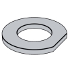
metal washers; technical delivery conditions
Steel flat products; Hot rolled plate 3 to 150 mm thick; Permissible deviations of dimension, weight and form
Flat products of steel; cold rolled steel strip; dimensions, tolerances on dimensions and form.
Commercial vehicles - Wheel-hub attachment dimensions
Corrosion of metals and alloys - Corrosivity of atmospheres - Guiding values for the corrosivity categories
Tools for pressing - Elastomer pressure springs - Part 2: Specification of accessories
Hydraulic fluid power - Two-, three- and four-port screw-in cartridge valves - Cavities
Cold heading dies for fasteners - Specifications

Specification of Stamping Die Components
Specifications for parts and units of jigs and fixtures
Internal combustion engines - Cylinder head and flywheel nuts - Specifications
Timber structures - Dowel-type fasteners - Requirements
Aerospace series - Bolts, MJ threads, in heat resisting nickel base alloy NI-PH2601 (Inconel 718) - Classification: 1275 MPa (at ambient temperature)/650 °C - Technical specification
High-strength structural bolting assemblies for preloading - Part 1: General requirements
Flanges and their joints - Bolting - Part 3: Classification of bolt materials for steel flanges, class designated
Metallic products - Types of inspection documents
Flanges and their joints - bolting - Part 2: Classification of bolt materials for steel flanges, PN designated
Flanges and their joints - bolting - Part 1: Selection of bolting
Aerospace series - Inserts, screw thread, helical coil, self locking - Technical specification
Aerospace series - Inserts, screw thread, helical coil, self-locking - Assembly procedure
Specification for Selection of Steel Pipe Flanges , Gaskets and Bolting (PN designated)
Alloy and Carbon Steel Bolting for Use in the Petroleum and Natural Gas Industries
Standard Specification for Steel Transmission Tower Bolts, Zinc-Coated and Bare
Mechanical fixation component for waterproofing membrane roofing
Construction machinery and equipment Specification of high strength fasteners
Fastenersart - Standard - Cap Screws, Hex Bolts, and Hex Nuts
Steel Self-Drilling Tapping Screws
Technical conditions for threaded fasteners with adhesive coating-Part 1: Microencapsulated locking coating
Technical condions for threaded fasteners with adhesive coating-Part 2: Polyamlde locking coating
Technical Supply Conditions For Threaded Steel Fasteners - Part 1 General Requirements For Bolts, Screws And Studs
General data for machine screws and tapping screws
Plain nuts and slotted nuts - Part 1: General specification
Disc springs - Calculation