|
|
| No dimensional drawings!
Unit:
|
|
|
| No dimensional drawings!
Unit:
|
一、技術要求
主要指标
1.螺栓的機械性能分級按表1的規定。
表1
級别(标記) | 3.6 | 4.6 | 4.9 | 5.6 | 5.9 | 6.6 | 6.9 | 8.8 | 10.9 | 12.9 | |
抗拉強度σb min kgf/mm2 | 33 | 40 | 50 | 60 | 80 | 100 | 120 | ||||
屈服極限σs min kgf/mm2 | 18 | 24 | 36 | 30 | 45 | 36 | 54 | 64 | 90 | 108 | |
伸長率 % | δ5≥ | 25 | 20 | / | 20 | / | 16 | / | 12 | 9 | 8 |
δ1.8≥ | / | 30 | 10 | 30 | 10 | 24 | 10 | 15 | 13 | 12 | |
硬度 HB | 90~ | 110~ | 145~216 | 175~255 | 230~305 | 295~375 | 355~430 | ||||
推薦材料牌号 (大量生產) | 10 A2 | 15 A3 | 10 A2 | 25 35 | 15 A3 | 45 | 35 | 35 45 | 40Cr15MnVB | 30CrMnSi15MnVB | |
頭杆結合強度試驗 | 對不經熱處理的冷镦螺栓,需進行本項試驗。 試驗後支承面與螺杆交接處,不允許有裂縫。 | ||||||||||
注:① 在一般情況下,伸長率和屈服極限隻作為參考指标,由制造廠在生產工藝中控制。如用戶要求考核屈服極限和伸長率時,應在訂單中注明;
② 10.9、12.9級的硬度範圍分别相應于鉻鋼、鉻錳矽鋼。選用其他材料,與強度相對應的硬度按 GB 1172—74 的規定。
2. 螺拴機械性能分級的标記;
(1)标記由數字表示,笫一位數字為 σb min / 10,帶小數點的第二位數字為屈強比(σs min /σb min );
(2)按機械性能分級的螺栓,當d≥5mm和大于或等于4.6級時,應在產品上制出标記(與表1相同),但對相應尺寸标準的标記示例中允許省略機械性能标記的,并且小于或等于6.9級的螺栓,可不制出标記;
(3)标記應在頭部頂面或凹穴底面上制出。可為凸字或凹字,其大小由制造廠規定。
3. 當機械性能分級的規定不能滿足使用要求時,可按表2規定的材料選用。
表2
種類 | 牌号 | 标準編号 |
特種鋼 | 1Cr13、2Cr13 Cr17Ni2 1Cr18Ni9Ti | GB 1220-75 |
銅及其合金 | H62、HPb59-1 H62防磁、HPb59-1防磁 | YB 457-71 |
鋁及其合金 | LY8 LY10 |
|
注:① 不同冶煉及澆注方法制造的鋼材同樣可以采用。 ② “牌号”欄内每一通欄中所列各種材料,可以互相通用。 | ||
4. 螺栓上的螺紋:
(1)螺紋基本尺寸按 GB 196—63 的規定。螺紋公差按 GB 197—63 的規定;粗牙為2、3級;細牙為2、2a、3級,粗制螺拴僅按3級公差制造;
(2)螺紋側面的光潔度按表3的規定。内、外徑及螺尾和最初兩扣的光潔度不作規定;
表3
類别 | 側面光潔度 |
精制螺栓 | ▽5 |
粗制螺栓 | ▽3 |
注:當螺距(t)不大于0.5mm時,可不檢查光潔度。 | |
(3)螺紋表面不允許有裂縫。
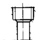
5. 支承面對螺杆軸心線的不垂直度(β)(圖1):
精制螺栓:β≤1°;
粗制螺栓:β≤2°。
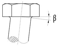
圖1
6. 螺栓應進行不直度的檢查。螺栓應順利落入檢驗模。
7. 當用戶提出要求時,可檢查精制螺栓的杆部脫碳層:
對5.9級及其以下的脫碳層應小于直徑的2.5%;
對6.6級及其以上的脫碳層應小于或等于直徑的1.5%.
一般指标
8. 螺杆上無螺紋部分的直徑:
(1) 精制等粗杆的螺栓,其允差按 GB 197—63 粗牙普通螺紋3級精度外徑的規定;
(2) 螺紋如系輾制,允許制成細杆,即小于螺紋外徑,其尺寸及允差由制造廠規定;
(3) 沉頭、半圓頭、導頸及活節螺栓的直徑d2小于螺紋外徑,其尺寸及允差由制造廠規定。
9. 螺紋空白:
注:螺紋空白系指螺杆上全部制出螺紋時,螺尾末端與支承面間(或與導頸、方頸末端間)的長度;或者鉸制孔用螺栓的螺尾與螺杆上無螺紋部分末端間的長度。精制螺栓不大于1.5t;
粗制螺栓不大于2t。
t——粗牙螺紋螺距。
10. 螺杆上不全部制出螺紋,并采用輾制螺紋工藝制造等粗杆的螺栓時,其螺尾末端與無螺紋部分末端間,允許有不大于2t(t——粗牙螺紋螺距)的頸部(圖2)。
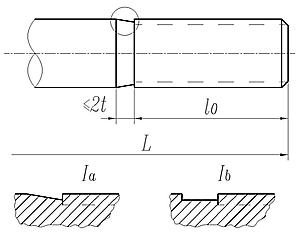
圖2
11. 螺紋長度(L0)的允差:
當d≤5mm時,+3t;
d>5mm時,+2t;
t——粗牙螺紋螺距。
14. 帶凹穴螺栓,其凹穴直徑D2≈(0.8~0.9)S、深度h≈(0.2~0.3)H、凹穴底部允許制成凹球面。凹穴螺拴對角的圓鈍應由生產工藝控制,即在距頂面寸1/3 H(頭高)處,D的尺寸公差不大于9級(GB 159—59)、單向負偏差。12. 螺尾及退刀槽按 GB 3—58 的規定。
13. 精制螺栓的螺杆末端按 GB 2—76 的規定制成倒角或球面,采用輾制螺紋工藝或粗制螺栓,可制成平端,允許有自然形成的圓穴、不顯著的壓扁。螺杆末端允許留有中心孔。
15. 螺栓的頂圓直徑(D1),頂面與側面交換處的倒角桉圖3的規定。
精制螺栓:D1≈0.95S;
粗制螺栓:D1≈0.9S。
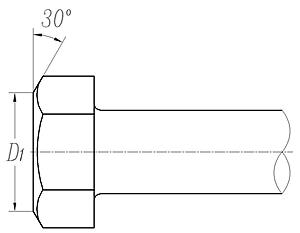
圖3
16. 六角頭和方頭螺拴的頭部側面對支承面的不垂直度(γ)(圖4):
精制螺栓:γ≤1°30';
粗制螺栓:γ≤2°。
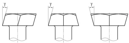
圖4
17. 各種半圓頭螺栓、螺栓方頸及導頸的末端,根據生產工藝的需要,允許按圖5制造。
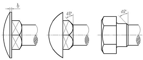
圖5
18. 螺栓頭對螺杆軸心線的不同軸度按表4的規定。
表4(mm)
d | 3 | 4 | 5 | 6 | 8 | 10 | 12 | (14) | 16 | (18) | 20 | (22) | 24 | (27) | 30 | 36 | 42 | 48 | |
不同軸度 | 精制螺栓 | 0.20 | 0.25 | 0.30 | 0.40 | 0.45 | 0.60 | ||||||||||||
粗制螺栓 | / | 0.3 | 0.4 | 0.5 | 0.6 | 0.7 | 0.8 | 1.0 | 1.2 | 1.4 | |||||||||
19. 頭部帶槽螺栓的槽對螺杆軸心線的不對稱度按表5的規定。
表5(mm)
d | 3 | 4 | 5 | 6 | 8 | 10 | 12 | (14) | 16 | (18) | 20 |
不對稱度 | 0.15 | 0.25 | 0.30 | 0.35 | 0.45 | ||||||
20. 螺杆帶孔螺拴的螺杆上孔的軸心線對螺杆軸心線的位移度按表6的規定。
表6(mm)
d | 6 | 8 | 10 | 12 | (14) | 16 | (18) | 20 | (22) | 24 | (27) | 30 | 36 | 42 | 48 |
位移度 | 0.20 | 0.25 | 0.30 | 0.45 | 0.50 | ||||||||||
21. 螺紋表面不允許有妨礙螺紋量規自由旋入的碰傷和毛刺;不允許有影響使用的雙牙尖、劃痕和扣不完整。
22. 螺拴表面不允許有影響使用的凹痕、毛刺、浮鏽、圓鈍、飛邊、燒傷和氧化皮。精制螺拴不允許有浮鏽和燒傷。在螺栓頂面30°倒角處不允許有影響使用的裂縫。
23. 在名稱中未注明“粗制”的,均為精制螺栓。精制與粗制是按尺寸精度、表面光潔度及技術要求劃分的,與生產工藝無關。
24. 上述規定以外的技術要求,由供需雙方協議。
二、測試方法
25. 螺栓的硬度試驗:
(1)一般可以硬度試驗結果作為抗拉強度的驗收依據。如有争議,應以抗拉強度試驗結果為準;
(2)硬度試驗部位,規定為螺杆末端。其試驗方法按 GB 231—63 的規定;
26. 抗拉強度試驗,在拉力試驗機上進行;
(1)将螺栓擰上螺母(或帶有内螺紋的專用夾具),再裝入拉力試驗機上進行試驗(圖6);
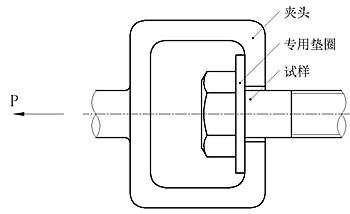
圖6
(2) 試驗中,當負荷達到σb min·A時,螺拴不得拉斷,當負荷大于σb min·A直至拉新後,亦不允許在頭部或支承面與螺杆交接處斷裂;
σb min——按表1或表2原材料的最小抗拉強度極限。

式中:
d2——螺紋中徑公稱尺寸;
d1——螺紋内徑公稱尺寸;
H——螺紋三角形高度。
(3)對大規格螺栓的抗拉強度試驗,根據設備條件,可以采取車削比例試祥進行。此時其伸長率按δ5,考核。
比例試樣的型式、尺寸按圖7的規定制取。
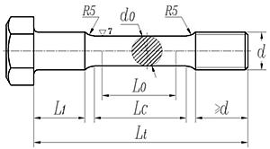
圖7
圖中:L0——5d0或5.65√A0;
A0——截面積;
d0——(3/4)d(螺紋直徑)<d0<d1(螺紋内徑);
Lc=L0+d0;
Lt=Lc+2R+(≥d)+L1。
其他技術要求按 GB 228—76《金屬拉力試驗法》的規定;
(4)對d≤5mm的螺栓,不進行抗拉強度試驗;
(5)對較短規格的螺栓,可采用由相同條件制成的同一直徑長規格的螺栓進行抗拉強度試驗。
27. 屈服極限,在進行抗拉強度試驗的同時求得。
28. 伸長率:用螺栓成品進行試驗,在抗拉強度試驗的同時求得,可按δ1.8或δ5考核。
(1)伸長率桉δ1.8考核時:

式中: L0≈1.8·d(螺紋内徑);
L1——試驗後的标距長度。
在試驗時将L0轉換為螺紋整數扣數進行測量,如表7。
表7
d(mm) | 6 | 8 | 10 | 12 | 14 | 16 | 18 | 20 | 22 | 24 | 27 | 30 |
拉力标距扣數 | 8 | 10 | 12 | 14 | ||||||||
注:本表适用于粗牙螺紋。 | ||||||||||||
(2) 伸長率按δ5 考核時:
當要求按δ5 考核伸長率時,其試樣按圖7制取。

式中, L0=5·d0;
L1——試驗後的标距長度。
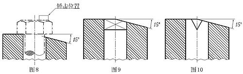
29. 頭與螺杆結合強度試驗——将螺栓裝入帶有15°斜面的檢驗模中,錘擊螺栓頭部,使支承面與斜面貼合。檢驗模及錘擊位巨如圖8~10所示。
(1)檢驗模的孔徑:
精制螺栓按 GB 152—76 精裝配的規定;
粗制螺栓按 GB 152—76 中等裝配的規定。
(2)如螺杆上全部制出螺紋時,應在制出螺紋前或在試件上去除螺紋後進行試驗。
當制出螺紋前進行試驗時,檢驗模的孔徑為螺紋公稱尺寸與“間隙”之和;當去除螺紋後進行試驗時,檢驗模的孔徑為螺紋内徑公稱尺寸與“間隙”之和;
“間隙”為螺紋外徑公稱尺寸與本條第(1)款相應檢驗模孔徑之差。
(3)頭部帶孔螺栓應在制出孔d4前進行試驗;
(4)方頸螺栓和帶榫螺栓的檢驗模如圖9及圖10所示。
30. 螺紋檢查——用螺紋量規和光滑極限量規(或萬能量具)進行。
(1)對下列螺紋的檢查, 僅用過端呈規和光滑極限晝規(或萬能量具)進行:
粗牙2級、細牙2a級,t≤0.35mm;
粗牙3級、細牙3級,t≤0.8mm。
三、驗收規則、包裝與标記(2)止端螺紋量規的旋入量不允許大于3-1/2扣,但當螺紋在4扣以内時,也不允許止規全部通過。
(3)螺紋如系輾制,最初兩扣外徑不作檢查。
31. 螺栓不直度檢查——用檢驗模進行.
(1)采用檢驗模的孔徑為:
精制螺栓 按GB 152—76 精裝配的規定;
粗制螺栓 按GB 152—76 中等裝配的規定。
(2)對精制螺栓,當用戶在訂單中提出要求時,應采用帶螺紋的檢驗模。其無螺紋部分的孔徑按GB 152—76 中等裝配的規定,螺紋按GB 197—63 規定的3級精度。
(3)檢驗摸的高度不小于被檢螺栓的長度。
(4)當螺杆長度L>10d或大于150mm時,亦可用平台及塞尺進行檢查。螺杆與平台的最大間隙應不大于檢驗模孔公稱直徑與螺杆公稱直徑之差。
32. “放扳手處”尺寸(S)的檢查——在最大尺寸部位進行。
33. 帶凹穴螺拴對角尺寸(D)的檢查——在距頂面1/3 H處,用專用卡闆或萬能量具進行。
34. 螺栓長度(L)的檢查,以短邊為準。
35. 驗收規則、包裝與标記按GB 90—76 的規定。
Specifications of high strength bolts with large hexagon head, large hexagon nuts, plain washers for steel structures
Self-tappingscrew connections - Specification ofthepilotholediameterand tighteningtorque
Composite sealing gasket material
Corrosion of metals and alloys - Corrosivity of atmospheres - Part 1 : Classification, determination and estimation
Corrosion of metals and alloys - Corrosivity of atmospheres - Part 2: Guiding values for the corrosivity categories
Steel wire ropes for general purposes
Specifications for spring washers - Conical spring washers
Specifications for retaining rings-Circlips
Hot formed helical compression springs - Technical Requirement
High-strength structural bolting assemblies for preloading - Part 1: General requirements
Cold coiled helical springs technical specifications - Part 1: Extension spring
Cold coiled helical springs technical specifications - Part 2: Compressions spring
Specification For Wire Thread Inserts
General specifications for packing of mechanical and electrical product
Fasteners - General requirements for bolts,screws,studs and nuts
24° Cone Connectors - Specification
Flared couplings - Specification
Specification of metallic ring-joint gaskets for steel pipe flanges
Specifications of high strength bolts with large hexagon head, large hexagon nuts, plain washers for steel structures
Specification of gauges for general purpose screw threads
Fasteners - Marking and packaging
Plain Washers for Bolts, Screws and Nuts - General Plan
Fasteners - Surface discontinuities - Bolts, screws and studs for general requirements
Fasteners-Surface discontinuities - Nuts
Fasteners - Surface discontinuities - Bolts, screws and studs for special requirements
Technical requirements for anchors
Specifications For Drive Rivets
Technical requirement for sets of torshear type high strength bolt hexagon nut and plain washer for steel structures
Specifications for parts and units of jigs and fixtures
Grease nipples and lubricating cups technical specification
Oil level indicators technical specification
Counterbores for hexagon socket head and slotted cheese head screws
Procurement Specification For Self-Locking Nuts
Specification for tab washer
Specifications for pins
Spcifications for ring - Cutting rings
Technical requirements of malleable cast iron pipe fittings
Fasteners - Part 27: Steel screws, bolts and studs made of steel with pre-adhesive coating - Technical specifications
metal washers; technical delivery conditions
Steel flat products; Hot rolled plate 3 to 150 mm thick; Permissible deviations of dimension, weight and form
Flat products of steel; cold rolled steel strip; dimensions, tolerances on dimensions and form.
Commercial vehicles - Wheel-hub attachment dimensions
Corrosion of metals and alloys - Corrosivity of atmospheres - Guiding values for the corrosivity categories
Tools for pressing - Elastomer pressure springs - Part 2: Specification of accessories
Hydraulic fluid power - Two-, three- and four-port screw-in cartridge valves - Cavities
Cold heading dies for fasteners - Specifications
Specification of Stamping Die Components
Specifications for parts and units of jigs and fixtures
Internal combustion engines - Cylinder head and flywheel nuts - Specifications
Timber structures - Dowel-type fasteners - Requirements
Aerospace series - Bolts, MJ threads, in heat resisting nickel base alloy NI-PH2601 (Inconel 718) - Classification: 1275 MPa (at ambient temperature)/650 °C - Technical specification
High-strength structural bolting assemblies for preloading - Part 1: General requirements
Flanges and their joints - Bolting - Part 3: Classification of bolt materials for steel flanges, class designated
Metallic products - Types of inspection documents
Flanges and their joints - bolting - Part 2: Classification of bolt materials for steel flanges, PN designated
Flanges and their joints - bolting - Part 1: Selection of bolting
Aerospace series - Inserts, screw thread, helical coil, self locking - Technical specification
Aerospace series - Inserts, screw thread, helical coil, self-locking - Assembly procedure
Specification for Selection of Steel Pipe Flanges , Gaskets and Bolting (PN designated)
Alloy and Carbon Steel Bolting for Use in the Petroleum and Natural Gas Industries
Standard Specification for Steel Transmission Tower Bolts, Zinc-Coated and Bare
Mechanical fixation component for waterproofing membrane roofing
Construction machinery and equipment Specification of high strength fasteners
Fastenersart - Standard - Cap Screws, Hex Bolts, and Hex Nuts
Steel Self-Drilling Tapping Screws
Technical conditions for threaded fasteners with adhesive coating-Part 1: Microencapsulated locking coating
Technical condions for threaded fasteners with adhesive coating-Part 2: Polyamlde locking coating
Technical Supply Conditions For Threaded Steel Fasteners - Part 1 General Requirements For Bolts, Screws And Studs
General data for machine screws and tapping screws
Plain nuts and slotted nuts - Part 1: General specification
Disc springs - Calculation