标準規定了卡套式管接頭的材料、壓力-溫度要求、标記方法、被連接管要求、扳擰尺寸與公差、結構與制造、性能和試驗要求、安裝說明、采購信息、标志等技術要求。
本标準适用于管子外徑為4mm~42mm、最大工作壓力為10~63MPa的液壓流體傳動和一般用途的管路系統。
注:在新設計的液壓流體動力系統中,應采用F型螺紋柱端。
5.1 符合卡套式管接頭标準的碳鋼管接頭,在介質溫度為-40℃~+120℃範圍使用時,應能承受表1和表2規定的工作壓力,不同工作壓力下24°錐密封焊接接管的壁厚應符合表3的規定。
5.2 除非另有規定,對于帶彈性密封件的管接頭,用于石油基液壓油系統時應給與特别的工作溫度範圍,其工作溫度範圍可能縮小,也可能完全不适用于其他流體。制造商可提供适用于不同介質能滿足溫度範圍要求的彈性密封件。
5.3 根據不同的壓力等級和使用條件,将卡套式管接頭分為以下三個系列:
——LL:超輕載系列;
——L:輕載系列;
——S:重載系列。
表1 用于液壓流體動力與一般用途卡套式管接頭的工作壓力
系列 | 管子外徑 mm | 卡套連接與錐體連接 | F型螺紋柱端 | ||
普通螺紋 | 最大工作壓力a MPab | 普通螺紋 | 最大工作壓力 MPa | ||
LL | 4 | M8×1 | 10 | / | / |
5 | M10×1 | 10 | / | / | |
6 | M10×1 | 10 | / | / | |
8 | M12×1 | 10 | / | / | |
L | 6 | M12×1.5 | 25 | M10×1 | 25 |
8 | M14×1.5 | 25 | M12×1.5 | 25 | |
10 | M16×1.5 | 25 | M14×1.5 | 25 | |
12 | M18×1.5 | 25 | M16×1.5 | 25 | |
(14) | M20×1.5 | 25 | M18×1.5 | 25 | |
15 | M22×1.5 | 25 | M18×1.5 | 25 | |
(16) | M24×1.5 | 25 | M20×1.5 | 25 | |
18 | M26×1.5 | 16 | M22×1.5 | 16 | |
22 | M30×2 | 16 | M27×2 | 16 | |
28 | M36×2 | 10 | M33×2 | 10 | |
35 | M45×2 | 10 | M42×2 | 10 | |
42 | M52×2 | 10 | M48×2 | 10 | |
S | 6 | M14×1.5 | 63 | M12×1.5 | 63 |
8 | M16×1.5 | 63 | M14×1.5 | 63 | |
10 | M18×1.5 | 63 | M16×1.5 | 63 | |
12 | M20×1.5 | 63 | M18×1.5 | 63 | |
(14) | M22×1.5 | 63 | M20×1.5 | 63 | |
16 | M24×1.5 | 40 | M22×1.5 | 40 | |
20 | M30×2 | 40 | M27×2 | 40 | |
25 | M36×2 | 40 | M33×2 | 40 | |
30 | M42×2 | 25 | M42×2 | 25 | |
38 | M52×2 | 25 | M48×2 | 25 | |
注1:F型螺紋柱端按附錄A。 注2:對于更高壓力和動态應用,應咨詢制造商。 注3:盡可能不采用括号内的規格。 | |||||
a 設計系數:4:1。 b 1MPa=10bar=106N/m2=106Pa。 | |||||
表2 用于一般用途卡套式管接頭的工作壓力
系列 | 管子 外徑 mm | 卡套連接與 錐體連接 | E型螺紋柱端 | B型螺紋柱端 | A型螺紋柱端 | 錐螺紋柱端 | |||||||
普通螺紋 | 最大 工作 壓力a MPab | 普通螺紋 | 最大 工作 壓力a MPab | 普通螺紋 | 最大 工作 壓力a MPab | 普通螺紋 | 55° 非密封管螺紋 | 最大 工作 壓力a MPab | 55° 密封管螺紋 | 60° 密封管螺紋 | 最大 工作 壓力a MPab | ||
LL | 4 | M8×1 | 10 | / | / | M8×1 | 10 | M8×1 | G1/8 | 10 | R1/8 | NPT1/8 | 10 |
5 | M10×1 | 10 | / | / | M8×1 | 10 | M8×1 | G1/8 | 10 | R1/8 | NPT1/8 | 10 | |
6 | M10×1 | 10 | / | / | M10×1 | 10 | M10×1 | G1/8 | 10 | R1/8 | NPT1/8 | 10 | |
8 | M12×1 | 10 | / | / | M10×1 | 10 | M10×1 | G1/8 | 10 | R1/8 | NPT1/8 | 10 | |
L | 6 | M12×1.5 | 25 | M10×1 | 25 | M10×1 | 25 | M10×1 | G1/8 | 25 | R1/8 | NPT1/8 | 25 |
8 | M14×1.5 | 25 | M12×1.5 | 25 | M12×1.5 | 25 | M12×1.5 | G1/4 | 25 | R1/4 | NPT1/4 | 25 | |
10 | M16×1.5 | 25 | M14×1.5 | 25 | M14×1.5 | 25 | M14×1.5 | G1/4 | 25 | R1/4 | NPT1/4 | 25 | |
12 | M18×1.5 | 25 | M16×1.5 | 25 | M16×1.5 | 25 | M16×1.5 | G3/8 | 25 | R3/8 | NPT3/8 | 25 | |
(14) | M20×1.5 | 25 | M18×1.5 | 25 | M18×1.5 | 25 | M18×1.5 | G1/2 | 25 | R1/2 | NPT1/2 | 25 | |
15 | M22×1.5 | 25 | M18×1.5 | 25 | M18×1.5 | 25 | M18×1.5 | G1/2 | 25 | R1/2 | NPT1/2 | 25 | |
(16) | M24×1.5 | 25 | M20×1.5 | 25 | M20×1.5 | 25 | M20×1.5 | G1/2 | 25 | R1/2 | NPT1/2 | 25 | |
18 | M26×1.5 | 16 | M22×1.5 | 16 | M22×1.5 | 16 | M22×1.5 | G1/2 | 16 | R1/2 | NPT1/2 | 16 | |
22 | M30×2 | 16 | M26×1.5 | 16 | M26×1.5 | 16 | M26×1.5 | G3/4 | 16 | R3/4 | NPT3/4 | 16 | |
28 | M36×2 | 10 | M33×2 | 10 | M33×2 | 10 | M33×2 | G1 | 10 | R1 | NPT1 | 10 | |
35 | M45×2 | 10 | M42×2 | 10 | M42×2 | 10 | M42×2 | G1-1/4 | 10 | R1-1/4 | NPT1-1/4 | 10 | |
42 | M52×2 | 10 | M48×2 | 10 | M48×2 | 10 | M48×2 | G1-1/2 | 10 | R1-1/2 | NPT1-1/2 | 10 | |
S | 6 | M14×1.5 | 63 | M12×1.5 | 63 | M12×1.5 | 40 | M12×1.5 | G1/4 | 63 | R1/4 | NPT1/4 | 40 |
8 | M16×1.5 | 63 | M14×1.5 | 63 | M14×1.5 | 40 | M14×1.5 | G1/4 | 63 | R1/4 | NPT1/4 | 40 | |
10 | M18×1.5 | 63 | M16×1.5 | 63 | M16×1.5 | 40 | M16×1.5 | G3/8 | 63 | R3/8 | NPT3/8 | 40 | |
12 | M20×1.5 | 63 | M18×1.5 | 63 | M18×1.5 | 40 | M18×1.5 | G1/2 | 63 | R1/2 | NPT1/2 | 40 | |
(14) | M22×1.5 | 63 | M20×1.5 | 63 | M20×1.5 | 40 | M20×1.5 | G1/2 | 63 | R1/2 | NPT1/2 | 40 | |
16 | M24×1.5 | 40 | M22×1.5 | 40 | M22×1.5 | 40 | M22×1.5 | G3/4 | 40 | R3/4 | NPT3/4 | 40 | |
20 | M30×2 | 40 | M27×2 | 40 | M27×2 | 40 | M27×2 | G3/4 | 40 | R3/4 | NPT3/4 | 40 | |
25 | M36×2 | 40 | M33×2 | 40 | M33×2 | 25 | M33×2 | G1 | 40 | R1 | NPT1 | 25 | |
30 | M42×2 | 25 | M42×2 | 25 | M42×2 | 16 | M42×2 | G1-1/4 | 25 | R1-1/4 | NPT1-1/4 | 16 | |
38 | M52×2 | 25 | M48×2 | 25 | M48×2 | 16 | M48×2 | G1-1/2 | 25 | R1-1/2 | NPT1-1/2 | 16 | |
注1:A型和E型螺紋柱端應符合GB/T 19674.2;B型螺紋柱端應符合GB/T 19674.3。 注2:對于更高壓力和動态應用,應咨詢制造商。 注3:盡可能不采用括号内的規格。 | |||||||||||||
a 設計系數:4:1。 b 1MPa=10bar=106N/m2=106Pa。 | |||||||||||||
表3 24°錐密封焊接接管的壁厚
系列 | 管子 外徑 mm | 最大工作壓力/MPa | |||||||||||
10 | 16 | 25 | 31.5 | 40 | 63 | ||||||||
内徑 | 壁厚 | 内徑 | 壁厚 | 内徑 | 壁厚 | 内徑 | 壁厚 | 内徑 | 壁厚 | 内徑 | 壁厚 | ||
L | 6 | 3 | 1.5 | 3 | 1.5 | 3 | 1.5 |
| |||||
8 | 5 | 1.5 | 5 | 1.5 | 5 | 1.5 | |||||||
10 | 7 | 1.5 | 7 | 1.5 | 7 | 1.5 | |||||||
12 | 8 | 2 | 8 | 2 | 8 | 2 | |||||||
(14) | 10 | 2 | 10 | 2 | 10 | 2 | |||||||
15 | 10 | 2.5 | 10 | 2.5 | 10 | 2.5 | |||||||
(16) | 11 | 2.5 | 11 | 2.5 | 11 | 2.5 | |||||||
18 | 13 | 2.5 | 13 | 2.5 |
| ||||||||
22 | 17 | 2.5 | 17 | 2.5 | |||||||||
28 | 23 | 2.5 |
| ||||||||||
35 | 29 | 3 | |||||||||||
42 | 36 | 3 | |||||||||||
S | 6 | 2.5 | 1.75 | 2.5 | 1.75 | 2.5 | 1.75 | 2.5 | 1.75 | 2.5 | 1.75 | 2.5 | 1.75 |
8 | 4 | 2 | 4 | 2 | 4 | 2 | 4 | 2 | 4 | 2 | 4 | 2 | |
10 | 6 | 2 | 6 | 2 | 6 | 2 | 6 | 2 | 6 | 2 | 5 | 2.5 | |
12 | 8 | 2 | 8 | 2 | 8 | 2 | 8 | 2 | 7 | 2.5 | 6 | 3 | |
(14) | 9 | 2.5 | 9 | 2.5 | 9 | 2.5 | 9 | 2.5 | 8 | 3 | 7 | 3.5 | |
16 | 11 | 2.5 | 11 | 2.5 | 11 | 2.5 | 11 | 2.5 | 10 | 3 |
| ||
20 | 14 | 3 | 14 | 3 | 14 | 3 | 14 | 3 | 12 | 4 | |||
25 | 19 | 3 | 19 | 3 | 19 | 3 | 17 | 4 | 16 | 4.5 | |||
30 | 24 | 3 | 24 | 3 | 22 | 4 |
| ||||||
38 | 32 | 3 | 32 | 3 | 28 | 5 | |||||||
注1:對于超出本标準規定壓力-溫度的應用,應咨詢制造商。 注2:盡可能不采用括号内的規格。 | |||||||||||||
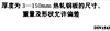
被連接碳鋼鋼管應采用符合GB/T 3639規定的低碳鋼正火态(NBK)無縫鋼管;不鏽鋼管應符合ISO 1127規定的退火态無縫鋼管。如果使用其他材料,由供需雙方确定。
鍛制扳擰對邊尺寸小于或等于24mm時的極限偏差為0,-0.8mm,大于24mm時的極限偏差為0,-1.0mm。
六方對邊尺寸S的公差應符合GB/T 3103.1的B級產品耍求。六方對角尺寸應不小于1.092S,扳擰邊長應不小于0.43S.如果無另外規定或标注。六方應倒角10°~30°,倒角直徑應等于六方對邊尺寸S,倒角直徑公差應0,-0.4mm。
外型結構:卡套式管接頭型式與尺寸應符合相應标準的要求。标準中未規定的結構尺寸由制造商确定,但應盡量減少流體阻力。
尺寸:标準中規定的尺寸是指包括鍍層或表面處理層厚度在内的成品尺寸,所有未注尺寸公差應為±0.4mm,卡套端的24°内錐座對其外螺紋中徑的圓跳動公差應為0.25mm,柱端螺紋中徑對密封端面的垂直度公差應為0.10mm。
通道公差:接頭體通道從兩頭加工時,彙合點的不重合偏差不得大于0.4mm,交叉通道的交彙橫截面積不得低于規定的最小通道截面積。
角度公差:規格不大于10mm的彎通、三通和四通的端口軸線的角度公差應為±2.5°,規格大于10mm 的彎通、三通和四通的端口軸線的角度公差應為±1.5°。
螺紋:普通螺紋應符合GB/T 193的規定,外螺紋公差應符合GB/T 197的6g級規定,内螺紋公差應符合GB/T 197的6H級規定,端面應倒角。螺紋收尾、肩距、退刀槽應符合GB/T 3的規定。電鍍後,外螺紋用6h級通規驗收。
55°非密封管螺紋應符合GB/T 7307的規定,外螺紋公差為A級,端面應倒角。
55°密封管螺紋應符合GB/T 7306.1或GB/T 7306.2的規定,端面應倒角。
60°密封管螺紋應符合GB/T 12716的規定,端面應倒角。
制造質量:所有接頭體和配件不應有裂紋、氣孔、毛剌、銳邊等。接頭體24°内外錐面和組合接頭體、可調向接頭體及錐密封體的O形圈溝槽表面粗糙度Ra≤3.2µm。不進行機械加工的零件表面允許有不超過其尺寸公差一半的凹陷和壓痕。未标注要求的所有機械加工表面的粗糙度Ra≤6.3µm。所有未注棱邊應倒鈍角,倒角尺寸不應大于0.15mm。
表面處理:如果供需雙方沒有其他協議,所有碳鋼零件的外表面和螺紋應鍍塗适當材料,通過72h中性鹽霧試驗。除下列區域外的任何鹽霧試驗紅鏽斑都應視為鍍塗不合格。
——孔内壁表面;
——在批量生產的鍍塗操作中或交付運輸中有可能碰傷的六角頂、齒狀結構頂、螺紋牙頂等;
——折、擴、彎或其他鍍後成型操作有損傷鍍塗的區域;
——試驗中的懸挂或固定處(有可能有鹽霧淤積)。
需焊接的零件應塗油膜或磷化或經其他不影響焊接的防鏽處理。
Specifications of high strength bolts with large hexagon head, large hexagon nuts, plain washers for steel structures
Self-tappingscrew connections - Specification ofthepilotholediameterand tighteningtorque
Composite sealing gasket material
Corrosion of metals and alloys - Corrosivity of atmospheres - Part 1 : Classification, determination and estimation
Corrosion of metals and alloys - Corrosivity of atmospheres - Part 2: Guiding values for the corrosivity categories
Steel wire ropes for general purposes
Specifications for spring washers - Conical spring washers
Specifications for retaining rings-Circlips
Hot formed helical compression springs - Technical Requirement
High-strength structural bolting assemblies for preloading - Part 1: General requirements
Cold coiled helical springs technical specifications - Part 1: Extension spring
Cold coiled helical springs technical specifications - Part 2: Compressions spring
Specification For Wire Thread Inserts
General specifications for packing of mechanical and electrical product

Fasteners - General requirements for bolts,screws,studs and nuts
Flared couplings - Specification
Specification of metallic ring-joint gaskets for steel pipe flanges
Specifications of high strength bolts with large hexagon head, large hexagon nuts, plain washers for steel structures

Specification of gauges for general purpose screw threads
Fasteners - Marking and packaging
Plain Washers for Bolts, Screws and Nuts - General Plan
Fasteners - Surface discontinuities - Bolts, screws and studs for general requirements
Fasteners-Surface discontinuities - Nuts
Fasteners - Surface discontinuities - Bolts, screws and studs for special requirements
Technical requirements for anchors
Specifications For Drive Rivets
Technical requirement for sets of torshear type high strength bolt hexagon nut and plain washer for steel structures
Specifications for parts and units of jigs and fixtures
Grease nipples and lubricating cups technical specification
Oil level indicators technical specification
Counterbores for hexagon socket head and slotted cheese head screws
Procurement Specification For Self-Locking Nuts
Specification for tab washer

Specifications for pins
Spcifications for ring - Cutting rings
Technical requirements of malleable cast iron pipe fittings
Fasteners - Part 27: Steel screws, bolts and studs made of steel with pre-adhesive coating - Technical specifications
metal washers; technical delivery conditions
Steel flat products; Hot rolled plate 3 to 150 mm thick; Permissible deviations of dimension, weight and form

Flat products of steel; cold rolled steel strip; dimensions, tolerances on dimensions and form.
Commercial vehicles - Wheel-hub attachment dimensions
Corrosion of metals and alloys - Corrosivity of atmospheres - Guiding values for the corrosivity categories
Tools for pressing - Elastomer pressure springs - Part 2: Specification of accessories
Hydraulic fluid power - Two-, three- and four-port screw-in cartridge valves - Cavities
Cold heading dies for fasteners - Specifications

Specification of Stamping Die Components
Specifications for parts and units of jigs and fixtures
Internal combustion engines - Cylinder head and flywheel nuts - Specifications
Timber structures - Dowel-type fasteners - Requirements
Aerospace series - Bolts, MJ threads, in heat resisting nickel base alloy NI-PH2601 (Inconel 718) - Classification: 1275 MPa (at ambient temperature)/650 °C - Technical specification
High-strength structural bolting assemblies for preloading - Part 1: General requirements
Flanges and their joints - Bolting - Part 3: Classification of bolt materials for steel flanges, class designated
Metallic products - Types of inspection documents
Flanges and their joints - bolting - Part 2: Classification of bolt materials for steel flanges, PN designated
Flanges and their joints - bolting - Part 1: Selection of bolting
Aerospace series - Inserts, screw thread, helical coil, self locking - Technical specification
Aerospace series - Inserts, screw thread, helical coil, self-locking - Assembly procedure
Specification for Selection of Steel Pipe Flanges , Gaskets and Bolting (PN designated)
Alloy and Carbon Steel Bolting for Use in the Petroleum and Natural Gas Industries
Standard Specification for Steel Transmission Tower Bolts, Zinc-Coated and Bare
Mechanical fixation component for waterproofing membrane roofing
Construction machinery and equipment Specification of high strength fasteners
Fastenersart - Standard - Cap Screws, Hex Bolts, and Hex Nuts
Steel Self-Drilling Tapping Screws
Technical conditions for threaded fasteners with adhesive coating-Part 1: Microencapsulated locking coating
Technical condions for threaded fasteners with adhesive coating-Part 2: Polyamlde locking coating
Technical Supply Conditions For Threaded Steel Fasteners - Part 1 General Requirements For Bolts, Screws And Studs
General data for machine screws and tapping screws
Plain nuts and slotted nuts - Part 1: General specification
Disc springs - Calculation