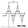
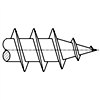
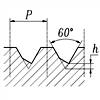
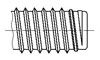
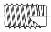
1.1 外螺紋收尾和肩距的型式與尺寸按圖 1 和表 1 的規定。螺紋收尾的牙底圓弧半徑不應小于對完整螺紋規定的最小牙底圓弧半徑。
表 1 (mm)
| 螺距 P | 收尾 x (max) | 肩距 a (max) | |||
| 一般 | 短的 | 一般 | 長的 | 短的 | |
| 0.2 | 0.5 | 0.25 | 0.6 | 0.8 | 0.4 |
| 0.25 | 0.6 | 0.3 | 0.75 | 1 | 0.5 |
| 0.3 | 0.75 | 0.4 | 0.9 | 1.2 | 0.6 |
| 0.35 | 0.9 | 0.45 | 1.05 | 1.4 | 0.7 |
| 0.4 | 1 | 0.5 | 1.2 | 1.6 | 0.8 |
| 0.45 | 1.1 | 0.6 | 1.35 | 1.8 | 0.9 |
| 0.5 | 1.25 | 0.7 | 1.5 | 2 | 1 |
| 0.6 | 1.5 | 0.75 | 1.8 | 2.4 | 1.2 |
| 0.7 | 1.75 | 0.9 | 2.1 | 2.8 | 1.4 |
| 0.75 | 1.9 | 1 | 2.25 | 3 | 1.5 |
| 0.8 | 2 | 1 | 2.4 | 3.2 | 1.6 |
| 1 | 2.5 | 1.25 | 3 | 4 | 2 |
| 1.25 | 3.2 | 1.6 | 4 | 5 | 2.5 |
| 1.5 | 3.8 | 1.9 | 4.5 | 6 | 3 |
| 1.75 | 1.3 | 2.2 | 5.3 | 7 | 3.5 |
| 2 | 5 | 2.5 | 6 | 8 | 4 |
| 2.5 | 6.3 | 3.2 | 7.5 | 10 | 5 |
| 3 | 7.5 | 3.8 | 9 | 12 | 6 |
| 3.5 | 9 | 4.5 | 10.5 | 14 | 7 |
| 4 | 10 | 5 | 12 | 16 | 8 |
| 4.5 | 11 | 5.5 | 13.5 | 18 | 9 |
| 5 | 12.5 | 6.3 | 15 | 20 | 10 |
| 5.5 | 14 | 7 | 16.5 | 22 | 11 |
| 6 | 15 | 7.5 | 18 | 24 | 12 |
| 參考值 | ≈2.5 P | ≈1.25 P | ≈3 P | =4 P | =2 P |

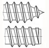
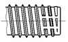
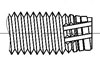
1.2 外螺紋退刀槽的型式和尺寸按圖 2 和表 2 的規定。過度角(α)不應小于30°。
| 螺距 P | g2 (max) | g1 (min) | dg | r ≈ |
| 0.25 | 0.75 | 0.4 | d-0.4 | 0.12 |
| 0.3 | 0.9 | 0.5 | d-0.5 | 0.16 |
| 0.35 | 1.05 | 0.6 | d-0.6 | 0.16 |
| 0.4 | 1.2 | 0.6 | d-0.7 | 0.2 |
| 0.45 | 1.35 | 0.7 | d-0.7 | 0.2 |
| 0.5 | 1.5 | 0.8 | d-0.8 | 0.2 |
| 0.6 | 1.8 | 0.9 | d-1 | 0.4 |
| 0.7 | 2.1 | 1.1 | d-1.1 | 0.4 |
| 0.75 | 2.25 | 1.2 | d-1.2 | 0.4 |
| 0.8 | 2.4 | 1.3 | d-1.3 | 0.4 |
| 1 | 3 | 1.6 | d-1.6 | 0.6 |
| 1.25 | 3.75 | 2 | d-2 | 0.6 |
| 1.5 | 4.5 | 2.5 | d-2.3 | 0.8 |
| 1.75 | 5.25 | 3 | d-2.6 | 1 |
| 2 | 6 | 3.4 | d-3 | 1 |
| 2.5 | 7.5 | 4.4 | d-3.6 | 1.2 |
| 3 | 9 | 5.2 | d-4.4 | 1.6 |
| 3.5 | 10.5 | 6.2 | d-5 | 1.6 |
| 4 | 12 | 7 | d-5.7 | 2 |
| 4.5 | 13.5 | 8 | d-6.4 | 2.5 |
| 5 | 15 | 9 | d-7 | 2.5 |
| 5.5 | 17.5 | 11 | d-7.7 | 3.2 |
| 6 | 18 | 11 | d-8.3 | 3.2 |
| 參考值 | ≈3 P | / | / | / |
注: 1. d 為螺紋公稱直徑代号。
2. dg 公差為:h13 ( d > 3mm );
h12 ( d ≤ 3mm )。
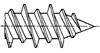
1.3 外螺紋始端端面的倒角一般為 45°,也可采用 60°或 30°倒角;倒角深度應大于或等于螺紋牙型高度。對搓(滾)絲加工的外螺紋,其始端不完整螺紋的軸向長度不能大于 2P。

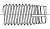
3.1 内螺紋收尾和肩距的型式與尺寸按 圖3 和 表3 的規定。
表 3 (mm)
| 螺距 P | 收尾 X max | 肩距 A | ||
| 一般 | 短的 | 一般 | 長的 | |
| 0.2 | 0.8 | 0.4 | 1.2 | 1.6 |
| 0.25 | 1 | 0.5 | 1.5 | 2 |
| 0.3 | 1.2 | 0.6 | 1.8 | 2.4 |
| 0.35 | 1.4 | 0.7 | 2.2 | 2.8 |
| 0.4 | 1.6 | 0.8 | 2.5 | 3.2 |
| 0.45 | 1.8 | 0.9 | 2.8 | 3.6 |
| 0.5 | 2 | 1 | 3 | 4 |
| 0.6 | 2.4 | 1.2 | 3.2 | 4.8 |
| 0.7 | 2.8 | 1.4 | 3.5 | 5.6 |
| 0.75 | 3 | 1.5 | 3.8 | 6 |
| 0.8 | 3.2 | 1.6 | 4 | 6.4 |
| 1 | 4 | 2 | 5 | 8 |
| 1.25 | 5 | 2.5 | 6 | 10 |
| 1.5 | 6 | 3 | 7 | 12 |
| 1.75 | 7 | 3.5 | 9 | 14 |
| 2 | 8 | 4 | 10 | 16 |
| 2.5 | 10 | 5 | 12 | 18 |
| 3 | 12 | 6 | 14 | 22 |
| 3.5 | 14 | 7 | 16 | 24 |
| 4 | 16 | 8 | 18 | 26 |
| 4.5 | 18 | 9 | 21 | 29 |
| 5 | 20 | 10 | 23 | 32 |
| 5.5 | 22 | 11 | 25 | 35 |
| 6 | 24 | 12 | 28 | 38 |
| 參考值 | = 4P | = 2P | ≈ 6~5P | ≈ 8~6.5P |

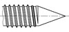
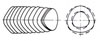
3.2 内螺紋退刀槽的型式與尺寸按 圖4 和 表4 的規定。
表 4 (mm)
| 螺距 P | G1 | Dg | R ≈ | |
| 一般 | 短的 | |||
| 0.5 | 2 | 1 | D+0.3 | 0.2 |
| 0.6 | 2.4 | 1.2 | 0.3 | |
| 0.7 | 2.8 | 1.4 | 0.4 | |
| 0.75 | 3 | 1.5 | 0.4 | |
| 0.8 | 3.2 | 1.6 | 0.4 | |
| 1 | 4 | 2 | D+0.5 | 0.5 |
| 1.25 | 5 | 2.5 | 0.6 | |
| 1.5 | 6 | 3 | 0.8 | |
| 1.75 | 7 | 3.5 | 0.9 | |
| 2 | 8 | 4 | 1 | |
| 2.5 | 10 | 5 | 1.2 | |
| 3 | 12 | 6 | 1.5 | |
| 3.5 | 14 | 7 | 1.8 | |
| 4 | 16 | 8 | 2 | |
| 4.5 | 18 | 9 | 2.2 | |
| 5 | 20 | 10 | 2.5 | |
| 5.5 | 22 | 11 | 2.8 | |
| 6 | 24 | 12 | 3 | |
| 參考值 | = 4P | = 2P | / | ≈0.5 P |
注:
1. “短”退刀槽僅在結構受限制時采用。
2. Dg 公差為 H13。
3. D 為螺紋公稱直徑代号。
3.3 内螺紋入口端面的倒角一般為 120°,也可采用 90°倒角;端面倒角直徑為:(1.05~1)D。

Locking threads with 30 degree wedge ramp
Miniature screw threads : Profiles , general plan and basic dimensions
General purpose metric screw threads - Tolerances
The blank diameters for rolling general purpose metric screw threads
Dryseal pipe threads with the thread angle of 60 degrees
Internal thread for wire thread inserts
Buttress Thread with the Flank Angles of 3 and 30 Degrees - Part 1: Profiles
Metric threads where pressure-tight joints are made on the threads
General purpose metric screw threads - Limits of sizes
Unified screw threads - General plan
Trapezoidal screw threads - Part 1: Profiles
General purpose metric screw threads - The plan for pipe systems

General purpose metric screw threads-Basic profile(ISO 68-1:1998, MOD)
General purpose metric screw threads - Basic dimenslons
General purpose metric screw threads - Limit deviations
General purpose metric screw threads - Preferable plan
General purpose metric screw threads - Limits of sizes for the screw threads of medium quality and preferable plan
General purpose metric screw threads - Limits of sizes for the screw threads of coarse quality and preferable plan
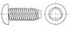
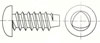
Tapping screws thread
Pipe Threads with 55 Degree Thread Angle where Pressure-Tight Joints are not Made on the Threads
Pipe threads with 55 degree thread angle where pressure-tight joints are made on the threads一 Parallel internal and taper external threads(eqv ISO 7-1:1994)
Pipe threads with 55 degree thread angle where pressure-tight joints are made on the threads一 Taper internal and external threads(eqv ISO 7-1:1994)
The interference-fit threads
The threads for transition fit
Pipe threads where pressure-tight joints are made on the threads

Screws thread shanks for thread forming screw-Metric coarse thread series
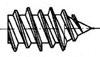
Specification for wood screws
Metric triangle lock with thread end

Metric Self-tapping Thread End
Whitworth pipe threads for pipe unions
Plastic threads
Threads and thread ends for tapping screws
ISO - Metric Trapezoidal Screw Threads
Thread and thread ends for wood screws
Bolted Connections with Reduced Shank; Metric Thread with Large Clearence, Nominal Dimensions and Limits
Aerospace - Lead and runout threads - Part 1: Rolled external threads
ISO metric trapezoidal screw threads - Basic and design profiles

ISO general purpose metric screw threads - Tolerances - Part 1: Principles and basic data

Fasteners─Bolts,screws and studs─Nominal lengths and thread lengths

ISO inch screw threads─Basic dimensions

Pipe threads where pressure-tight joints are not made on the threads
Tapping Screws Thread
ISO general purpose metric screw threads - General plan
ISO general purpose metric screw threads — Selected sizes for screws, bolts and nuts

Limits of sizes for general purpose external and internal screw threads

Deviations for constructional screw threads
Pipe threads where pressure-tight joints are made on the threads - Part 1: Dimensions, tolerances and designation

ISO general-purpose metric screw threads─Basic dimensions
HA Thread [Figure 2]
HB Thread [Figure 4]
Symmetrical thread HC [Figure 4]
Asymmetrical thread HD [Figure 6]
Tapping Screw Threads and Ends
Limit gauges for metric screw threads

Tapping screw threads and ends
Taper pipe threads
Limits of sizes and tolerances for metric coarse screw threads
Tapping Screw Threads and Ends
Locking Thread with 30° wedge ramp
The bar diameters for rolling general purpose screw threads
Special kind of fine screw for optical instruments

Dimensions of Threads and Points for Type AB and Type ABR Thread-forming Screws

Dimensions of Threads and Points for Type B and BP Thread-Forming Tapping Screws

Dimensions of Threads and Points for Type A Thread-Forming Tapping Screws
Thread Lengths for Type A, AB, B, BF, BP and BT Tapping Screws
Thread Lengths for Type C, D, F, G, T and TRS Tapping Screws
![Lag screw threads [Table 16]](https://imgcc.164580.com/upload/48/standard/2012/02/03/1328254371610499842.jpg)
Lag screw threads [Table 16]
AB self-tapping teeth
self-tapping teeth-B
Self-tapping teeth-BF
Triangle lock self-tapping teeth--D、F、G


Threaded rods(inch series) (A307, F1554, A193, CRES,F593,F468)
![Wood thread [Table 1]](https://imgcc.164580.com/upload/48/standard/2011/07/29/1311927213993228307.jpg)
Wood thread [Table 1]
![Wood thread [Table 1]](https://imgcc.164580.com/upload/48/standard/2011/04/29/1304063562598941856.jpg)
Wood thread [Table 1]
![Thread and body dimeters for wood screws [Table 1]](https://imgcc.164580.com/upload/48/standard/2024/12/23/1734937527164073998.jpg)
Thread and body dimeters for wood screws [Table 1]
Pipe threads where pressure tight joints are made on the threads - Part 1 : Taper external threads and parallel internal threads - Dimensions, tolerances and designation
US triangle lock thread-S type

Metric triangle lock thread-S type
Metric triangle lock thread-C type

Metric triangle lock thread-B type
Metric triangle lock thread-P type
![Thread and point details for Type Y thread cutting screws [TABLE 6]](https://imgcc.164580.com/upload/48/standard/2020/07/27/1595832347314908017.jpg)
Thread and point details for Type Y thread cutting screws [TABLE 6]
![Thread and point details for Type A threads [TABLE 23]](https://imgcc.164580.com/upload/48/standard/2020/07/27/1595832360911151243.jpg)
Thread and point details for Type A threads [TABLE 23]
Threaded insert, coated with precote 80 microcapsules recommended lengths
Screw Threads - UNJ Profile, Inch
Tapping thread for nylon lock
Screw Threads for Thread Forming Tapping Screws - Dimensions
ISO general purpose metric screw threads - General plan
Thread Lengths for Types A, AB, B, BF, BP, and BT Tapping Screws
Thread Lengths for Types C, D, F, G, T, and TRS Tapping Screws

Dimensions of Threads and Points for Types AB and ABR Thread-Forming Tapping Screws

Dimensions of Threads and Points for Type B and BP Thread-Forming Tapping Screws
Dimensions of Threads and Points for Type A Thread-Forming Tapping Screws