液壓傳動和通用連接件.ISO 261米制螺紋和O形密封圈的端口和螺柱端.第1部分:O形密封圈用帶截短外殼的端口 ISO 6149-1 - 2022
适用範圍
This document specifies dimensions for metric ports for use with the adjustable and non-adjustable stud ends as described in ISO 6149-2 and ISO 6149-3.
Ports in accordance with this document can be used at working pressures up to 63 MPa (630 bar) for non-adjustable stud ends and 40 MPa (400 bar) for adjustable stud ends. The permissible working pressure depends upon port size, materials, design, working conditions, application, etc. See ISO 6149-2 and ISO 6149-3 for pressure ratings.
NOTE The Introduction of this document gives recommendations for ports and stud ends to be used for new designs in hydraulic fluid power applications.
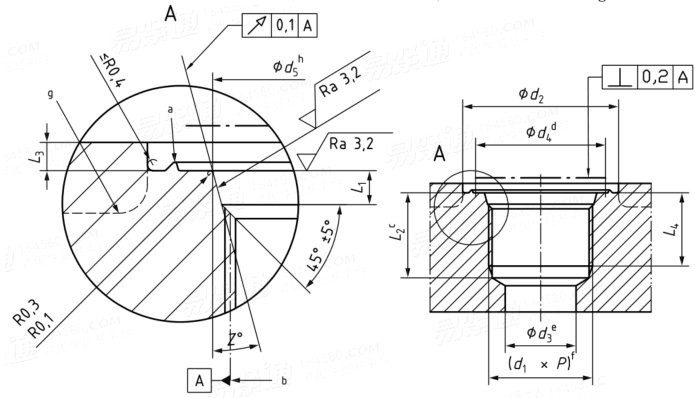
端口尺寸

螺紋① d1×P | d2 | d3② | d4 | d5 | L1 | L2③ | L3 | L4 | Z° | |
寬④ | 窄⑤ | |||||||||
min | min | 參考 | +0.1,0 | +0.4,0 | min | min | min | ±1° | ||
M8×1 | 17 | 14 | 3 | 12.5 | 9.1 | 2.2 | 11.5 | 1 | 10 | 12 |
M10×1 | 20 | 16 | 4.5 | 14.5 | 11.1 | 2.2 | 11.5 | 1 | 10 | 12 |
M12×1.5 | 23 | 19 | 6 | 17.5 | 13.8 | 2.4 | 14 | 1.5 | 11.5 | 15 |
M14×1.5⑥ | 25 | 21 | 7.5 | 19.5 | 15.8 | 2.4 | 14 | 1.5 | 11.5 | 15 |
M16×1.5 | 28 | 24 | 9 | 22.5 | 17.8 | 2.4 | 15.5 | 1.5 | 13 | 15 |
M18×1.5 | 30 | 26 | 11 | 24.5 | 19.8 | 2.4 | 17 | 2 | 14.5 | 15 |
M20×1.5⑦ | 33 | 29 | / | 27.5 | 21.8 | 2.4 | / | 2 | 14.5 | 15 |
M22×1.5 | 33 | 29 | 14 | 27.5 | 23.8 | 2.4 | 18 | 2 | 15.5 | 15 |
M27×2 | 40 | 34 | 18 | 32.5 | 29.4 | 3.1 | 22 | 2 | 19 | 15 |
M30×2 | 44 | 38 | 21 | 36.5 | 32.4 | 3.1 | 22 | 2 | 19 | 15 |
M33×2 | 49 | 43 | 23 | 41.5 | 35.4 | 3.1 | 22 | 2.5 | 19 | 15 |
M42×2 | 58 | 52 | 30 | 50.5 | 44.4 | 3.1 | 22.5 | 2.5 | 19.5 | 15 |
M48×2 | 63 | 57 | 36 | 55.5 | 50.4 | 3.1 | 25 | 2.5 | 22 | 15 |
M60×2 | 74 | 67 | 44 | 65.5 | 62.4 | 3.1 | 27.5 | 2.5 | 24.5 | 15 |
① Conforming to ISO 261, tolerance grade 6H in accordance with ISO 965-1. Tap drills in accordance with ISO 2306, class 6H. ② For reference only. Connecting hole application may require a different size. ③ The tap drill depths given require the use of a bottoming tap to produce the specified full thread lengths. Where standard taps are used, the tap drill depths shall be increased accordingly. ④ Spotface diameter with identification ridge. ⑤ Spotface diameter without identification ridge. ⑥ Preferred for diagnostic port applications. ⑦ For cartridge valve cavity applications only (see ISO 7789). | ||||||||||
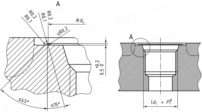
可選端口标識

螺紋 d1×P | d6 +0.5, 0 |
M8×1 | 14 |
M10×1 | 16 |
M12×1.5 | 19 |
M14×1.5 | 21 |
M16×1.5 | 24 |
M18×1.5 | 26 |
M20×1.5 | 29 |
M22×1.5 | 29 |
M27×2 | 34 |
M30×2 | 38 |
M33×2 | 43 |
M42×2 | 52 |
M48×2 | 57 |
M60×2 | 67 |
